Another 'how much will she defreck preas?'-Press calc
Moderators: Head Monkey, kelvin, bigKam, skidesmond, chrismp
- MontuckyMadman
- Posts: 2395
- Joined: Fri Jun 20, 2008 9:41 pm
Another 'how much will she defreck preas?'-Press calc
So I am looking at making another press.
15" wide
3 - 5" x 5" steel 3/8" thick.
Top and bottom with a cage around and most likely trussed front and back like kingwoods or twizz's.
2" x 2" in front that fold down with a pin and 2 sheer points and 1" strap welded on the back.
The whole press will be welded and the 5" x 5" will be stitch welded top and bottom to make a single more cohesive beam.
I just want to know potential deflection without the trussing.
8' opening 2 hoses blah blah blah.
Who wants to do the math at 50 psi to calc deflection.
I decided I would try google sketchup and made a drawing.
meh?
Tanks in advance!
this is a lot like my press
mine is 6x6 tube steel (5/16 thick) 2 top/2 bottom )stitich welded with 14" H beams welded in for sides. Each joint between the tube steel and the H beam has an extra gussett plate for re-inforcement. There is 2 inch V channel welded to the back solid and a 2x3 center post in the front with 3 grade 1/2" 8 bolt and 1 grade 5 bolt as a shear pin.
I have not done any calculations either but have also not built anything yet.
We put it on a mobile home axle and can tow it where ever it needs to be.
Fighting gravity on a daily basis
www.Whiteroomcustomskis.com
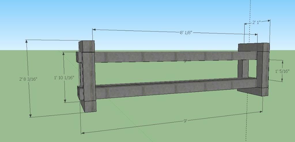
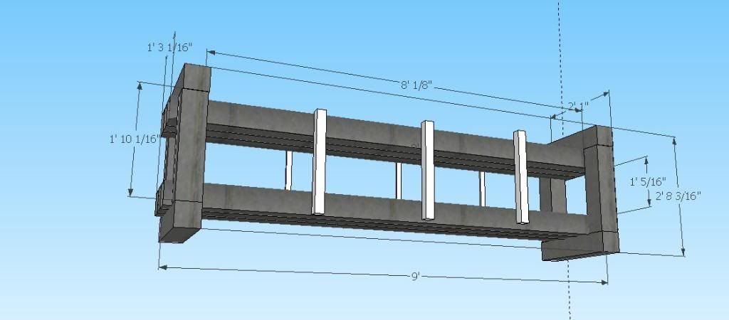
That inertia calc is for I beams. For a square hollow section, you basically calculate the inertia of the outer square and subtract the inertia of the inner square.
So outside is 5x5 = 5*5^3/12 = 52.08in^4
Inside = 5 - 2(3/8) square = (4.25)(4.25)^3/12 = 27.19in^4
Ixx = 52.08 - 27.19 = 24.89in^4
Since you have 3 beams above and below, triple that so Ixx = 24.89*3 =74.67in^4
At 50PSI you have 50 x 15" = 750lb/in
E = 29000000 PSI
L = 96"
y = 0.5h = 2.5"
Copied straight from http://www.engineeringtoolbox.com/beam- ... _1312.html
---------------------------------------------------------------------------
Unit Load - q : 750 (lb/in)
Total Load : 72000 (lb)
Length of Beam - L : 96 (in)
Moment of Inertia - I : 74.7 (in4)
Modulus of Elasticity - E : 29000000 (psi)
Perp. distance from neutral axis - y : 2.5 (in)
Support Force - R1 : 36000 (lb)
Support Force - R2 : 36000 (lb)
Maximum Stress - ? : 28927 (psi)
Maximum Deflection - ? : 0.38 (in)
--------------------------------------------------------------------------
Alternatively, you can find an inertia table here http://sketchup.engineeringtoolbox.com/ ... -c_79.html
They take 0.35" as the thickness, where I took 3/8" = 0.375"
Again, these are an estimated calc and likely to be high, as the pressure isn't fully distributed along the beams, only where the hoses press.
- MontuckyMadman
- Posts: 2395
- Joined: Fri Jun 20, 2008 9:41 pm
cool. That's what I needed to see.
The hoses would only be 12" on contact wide and maybe 76" long err 86" on contact so deflection could be less.
I will truss it because most of my cambers are really small so loosing a 1/4inch-1/2 inch in camber would be bad and not to mention tip and tail rise.
Really if I spent a whole lot of time trying to understand this I may be able but currently its over my head. Thanks.
-
- Posts: 2337
- Joined: Tue Apr 07, 2009 3:26 pm
- Location: Western Mass, USA
- Contact:
-
- Posts: 2204
- Joined: Tue Mar 07, 2006 8:25 pm
- Location: Kenmore, Wa USA
I think ingenuity is the word you're looking for And I agree, well done Vinman, that's damn clever.skidesmond wrote:Gold Star for inventiveness (is that aword?)! Put a tow hitch on it and you're in business!Vinman wrote:.....
We put it on a mobile home axle and can tow it where ever it needs to be.
actually it was my friend/welder's idea. Once the press is in the shop and on blocks the axle will be unbolted and removed.
I just got the joists for the floor done today and picked up $500 worth of insulation for $10 from a guy on craigslist. SCORE!!!!
Fighting gravity on a daily basis
www.Whiteroomcustomskis.com
-
- Posts: 2337
- Joined: Tue Apr 07, 2009 3:26 pm
- Location: Western Mass, USA
- Contact:
Yes, Ingenuity... Thanks Twizz! ( I guess I should have finished my coffee this morning )twizzstyle wrote:I think ingenuity is the word you're looking for And I agree, well done Vinman, that's damn clever.skidesmond wrote:Gold Star for inventiveness (is that aword?)! Put a tow hitch on it and you're in business!Vinman wrote:.....
We put it on a mobile home axle and can tow it where ever it needs to be.
I just got a hold of enough W12x26 to build a 2 ski or one snowboard press.
I ran the numbers and came up with .015" deflection @ 50 psi and 8 ft. of span. I'm no engineer and its been a while since college so I'm not sure if I did it right.
I'd like to build one similar to the one on the happy monkey site.
What do you guys think, am I in the ballpark?
Thanks in advance, awesome site!
art
- MontuckyMadman
- Posts: 2395
- Joined: Fri Jun 20, 2008 9:41 pm
in a free standing beam max defl=5PL^4/384EiMontuckyMadman wrote:So I found out this is going to be .25" thick steel.
Alex you round? What does this mean? I will truss in the center with three spans but raw deflection could be ?
in a continues beam it will be max defl=PL^4/384Ei
if initial span is divided in 4 parts, defl will be reduced by more than 256 times
optimum will be to have sorter end-spans (by about 0.7 -0.8 times) than the middle ones. but deflection will be enormously reduced anyway.
not an engineer, you might want to wait for a confirmation...
fa
Last edited by fa on Tue Nov 02, 2010 2:38 pm, edited 1 time in total.
-
- Posts: 26
- Joined: Fri Oct 29, 2010 4:51 pm
no, i didn't know that, interesting link
MM, if the 5x5s are cold-rolled, might be safe to cage them with frames to prevent skewing. (lower sketch)
Also, for the middle vertical supports, you might want to use flat bars instead of the tubular 2x2, as it will be easier to tide fit the pin through. (solid profiles are good when bolting or drilling & these members will only resist tension so no need to be hollowed). Flat bars match nice with L 's
just my thoughts, good luck with it!
[/img]