
hey can we get some pics of our modifications?
Really want to build my own, but you say mdf not worth it.
have a lowwwww budget.
Our cnc router, finnaly being assembled
Moderators: Head Monkey, kelvin, bigKam, skidesmond, chrismp
-
MontuckyMadman

- Posts: 2395
- Joined: Fri Jun 20, 2008 9:41 pm
-
jvangelder
- Posts: 181
- Joined: Tue Jul 07, 2009 4:41 pm
- Location: Southern NH

thats what it will look like with jgro mdf uprights and the aluminum bearings ways, 8020 with the 1/4x3 1018crs guide and our rack and pinion. The x axis isnt modeled, however the gear rack is just mounted right ontop of the center brace of the uprights and the motor is mounted on the x gantry
As for cost, we are maby $1200 in with mdf, nema34 steppers, an ebay stepper drive and misc hardware. that is with all machining done for free.
Aluminium plate in place of the mdf so far would have added maby 4-500 in total cost, not really a lot considering the increased rigidity.
-Jacob
-
MontuckyMadman
- Posts: 2395
- Joined: Fri Jun 20, 2008 9:41 pm
im confused as to what linear bearing you are using for the x axis.
Is it the PE slidey ones from 80/20? I can find that sku numbe.
I dont that type of rail stock from them. Im new to this.
wait don't you mean the y axis isn't modeled?
x long, y across, z up and down right?
I see an x with a rack and pinion and a linear bearing assembly.
Is it the PE slidey ones from 80/20? I can find that sku numbe.
I dont that type of rail stock from them. Im new to this.
wait don't you mean the y axis isn't modeled?
x long, y across, z up and down right?
I see an x with a rack and pinion and a linear bearing assembly.
sammer wrote: I'm still a tang on top guy.
-
jvangelder
- Posts: 181
- Joined: Tue Jul 07, 2009 4:41 pm
- Location: Southern NH

The linear bearing on the Y will be a piece of 1/4x3 cold drawn steel, if i have to ill get it Blanchard ground.
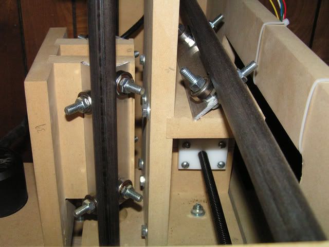
the large block that looks like a C is 3 pieces of aluminum (it was 1/4 the cost in material going 3pc vs 1pc) holds 12 roller skate bearings, 6 of which (the ones on top and the ones on the back side of the block respectively) are ridgedly mounted with slip-fit holes for ground shaft's for the bearings to ride on. The other 6 bearings, the ones on the face and the ones on the base of the block have slots for the shafts to slide though to allow for adjustment. I will use setscew's with jamnuts with springs above them to push on the shafts to take up adjustment in the assembly
As for the X, currently its the original jgro design which uses steel pipe as guides and the bearings are mounted on angle iron so they are 90* apart and huge the pipe
here is a picture of someone elses jgro build with the original bearing and guide design
Once the Y axis is complete and proven on our machine, we will build a similar design for the x axis and probably widen it as right now we only have 15" of use able travel.
At the same time of the x axis overhall the z will be converted to something more ridged and get a true acme leadscew and ballnut to replace the 3/4 homedepot threaded rod we are using now
Our machine has the long Y axis, while not orthodox makes it easier to compare the original design to what we have now, as its the jgro's Y axis we we enlarged
-Jacob