Page 1 of 1
Designing Multi -Radius Sidecut AutoCAD/Fusion 360
Posted: Thu Mar 18, 2021 7:37 am
by vinnycenze
I am having trouble designing a progressive sidecut on my board. I am looking to have a wider radius in middle and then tighter radius with a blend under foot (something around 7.1/7.9/7.1).
It seems I am too new to this and unsure where or how to blend these radiuses along the sidecut.. the two radius in the picture (example purposes) are close but I cant seem to figure out how to blend smoothly underfoot.
Might be a complicated/loaded question but its been a month of trials and it was worth a shot asking.
Also extemely open to hear how others do this and not my method.
Re: Designing Multi -Radius Sidecut AutoCAD/Fusion 360
Posted: Fri Mar 19, 2021 5:43 am
by comet
Hard to tell what is going on in your drawing there, but it looks like you have two complete arcs for each radius running tip to tail. What you really need is to have a front arc segment at the larger radius which is tangent to a separate arc in the middle which is smaller radius, and then that is tangent again to the rear segment which matches the front. I'm not as familiar with the specific commands in AutoCAD, but I did a quick Solidworks sketch to show what I mean. You can see the tangent relations between arcs and that the two larger ones are equal radius. Or maybe I'm not understanding your issue?
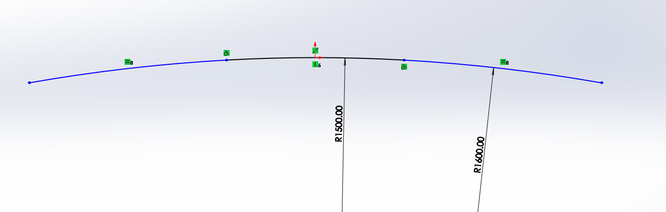
- Capture.PNG (60.1 KiB) Viewed 3704 times
Re: Designing Multi -Radius Sidecut AutoCAD/Fusion 360
Posted: Sun Mar 21, 2021 2:56 am
by vinman
When you connect the arcs, try selecting them and using the tangent constraint command. I think that should glen the arc together so thy are smooth at the junctions.
Re: Designing Multi -Radius Sidecut AutoCAD/Fusion 360
Posted: Tue Mar 23, 2021 12:49 pm
by vinnycenze
I appreciate both replies, It seems to blend them smoother on Fusion 360 - My version of CAD was the issue it seems(?)
My last question is more of an opinion I suppose.. When I blend with the tangents I want, where do i place these radiuses? Is it best two do two circles as Ive seen and place one at the midpoint of sidecut and then another after insert pack? Or is it a circle in a circle and tangent?
I apologize if this is vague, I just cant seem to get the desired outcome and dont know..
Re: Designing Multi -Radius Sidecut AutoCAD/Fusion 360
Posted: Wed Mar 24, 2021 10:58 am
by TimW
I have lousy Autocad skills, but what I always do is offset one segment with the radius for the next segment, and then draw the the next segment with the endpoint of the offset curve.
So in your example I'd first draw the 7.9 m segment, offset it by 7.1m, and then draw two 7.1m radius circles with the endpoints of the offset curve's as centre
Re: Designing Multi -Radius Sidecut AutoCAD/Fusion 360
Posted: Fri Mar 26, 2021 9:08 am
by vinnycenze
I suppose it is my cad software I am using, it does not allow tangent constraints on arcs/circle radiuses..
Are you setting the coordinates of the arc to the contact length (i.e 1170mm) and adding a radius (i.e 7.5) and then where the insert packs are adding another radius (i.e 8 ) to begin before or after the ref stance?
That is what i have been doing but the blend is not right and does not line up..
Is it possible to have an exploded view? I am so willing to get this down I will pay MONEY for a tutor!!

Re: Designing Multi -Radius Sidecut AutoCAD/Fusion 360
Posted: Sat Mar 27, 2021 3:44 am
by mammuth
Zoom in, measure and think again if its necessary to do this

You can also look into fibonacci curves
Re: Designing Multi -Radius Sidecut AutoCAD/Fusion 360
Posted: Mon Mar 29, 2021 4:28 am
by TimW
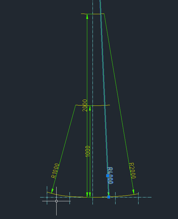
- radii.png (9.79 KiB) Viewed 3582 times
Maybe this makes it clearer. First draw the center section to where you want it to start and end. Offset it an amount equal to the next radius you want (in the case 1000 & 2000 mm), then draw the next radius with the endpoint of the offset line as centerpoint. (Centerlines indicate the transitions)
Re: Designing Multi -Radius Sidecut AutoCAD/Fusion 360
Posted: Mon Mar 29, 2021 4:31 am
by TimW
BTW I just draw circles that I trim, I do not use the radius command
Re: Designing Multi -Radius Sidecut AutoCAD/Fusion 360
Posted: Tue Jun 08, 2021 12:07 pm
by vinnycenze
Tim,
I never replied to you and I apologize.
This worked out so well!!! I appreciate the advice
Re: Designing Multi -Radius Sidecut AutoCAD/Fusion 360
Posted: Tue Jul 13, 2021 11:02 am
by Cadman
If I was to draw a multi tangent side cut shape, I start out putting my first radius at the waist. You can check to see if the radius is on the waist by drawing a vertical line using the center of the radius you just drew. Next I offset that vertical line by the length that I want the center radius to be. For example 300mm each side of the waist. Trim the radius to those two lines. Now draw a line from the end point of the center radius to the center of the radius at each end. Whatever radius you put at the tip is determined by what width you want at the tip. There are a number of different ways to draw the tip radius but to check to see if the two arcs are tangent, draw a point at the center of the tip radius. That point must by on the line that you drew from the end point of the center arc or it is not tangent by definition. Do the same thing for the 3rd radius at the tail.
Hopefully, that make a little sense. There are so many different ways to draw a tangent curve to another curve in each program. Tim is on the right track.