Just finished my planer based core profiler that uses spacers. So time for some pictures...
This is what the result looks like. The profiler is made out of 18 mm thick MDF. Over a length of two meters support blocks are placed every 40 mm (centre to centre), this leaves 24 mm of space to place the positioning blocks and spacers. This results in setting the height of the positioning blocks (thickness of the core) at 49 places, so it's a very adaptable construction.

The positioning blocks have exactly the same height and have two holes on top to mount a thin plate and grid tape to place the core at. On the other side (image below) a countersunk hole is made to place a M4 Rampa insert and have additional space for the bolt.

Zoom-out of positioning block...

Aluminium strip material is used to set the height.

The aluminium strip material varies in thickness from 0.5mm to 10.0mm


After adjusting the height a M4 screw is fastened from the bottom (middle of picture) to fix the spacers and positioning before going into the planer.
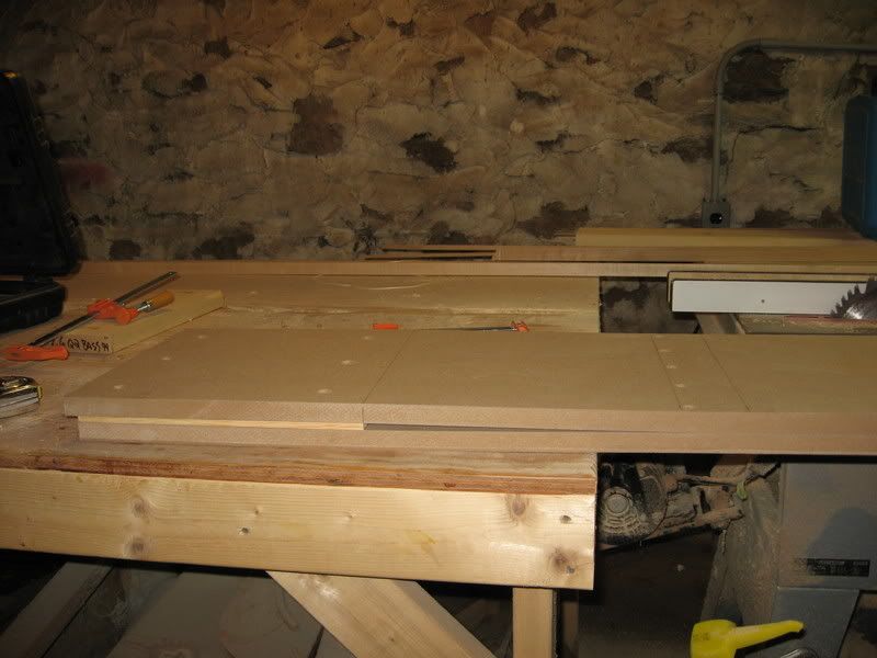
An overview of what is looks like with only 2 positioning blocks in place.

In the next weeks I will shape my new cores, glue the sidewalls to them and after some testing check out my new planer profiler. I will inform you about the result.
Buuk