
so with a bit more messing around I've kind of figured out my own way to set the waist where I want it to be and control the front and back arcs in the ski
to do this I create the wire frame as described above. Then I create a point 2mm on either side of the desired waist location.
Connect the tip and 2 waist points in the front 1/2 of the arc with the 3 pt. arc tool. Do the same for the back 1/2 of the arc.
Measure the curvatures and edit the tail width as needed to match or at least closely approximate the curvature in the front. Trim any overlapping lines.
or alter the tail width to what ever curvature you desire. this can give you the multi-radius designs that a few companies offer now.
I kind of like idea of the tighter curve of the front 1/2 of the ski with the longer curve of the back, especially in a ski with rocker-reverse sidecut in the tip and tail. This would lend itself to be turny when skied upfront and smeary, buttery when skied from mid-stance or slightly back.
I'm sure the circle method is easier but this works for me and gives me more control of my shapes.
CAD drawing tutorial
Moderators: Head Monkey, kelvin, bigKam, skidesmond, chrismp
Fighting gravity on a daily basis
www.Whiteroomcustomskis.com
www.Whiteroomcustomskis.com

sounds ok.
the big thing for me in my designing is that all the arcs meet tangentially so when they get cnc cut it is all smooth (helps mostly for edge bending transitions). if you are hand sanding then you prob sand out any small non tangential joins. i think your current method is non tangential, but prob that close to it that it doesn't really matter.
joining circles at their vertices guarantees that the arcs are tangential. for a multi radius sidecut just place the smaller radius circle's vertex at the waist point and then the larger radius circle's vertex at the same waist point then trim the excess. i will try and draw it up and take a picture.
Don't wait up, I'm off to kill Summer....
-
knightsofnii
- Posts: 1148
- Joined: Tue Jan 08, 2008 6:02 am
- Location: NJ USA
- Contact:
the version of snocad I have will not tangent the tips to the sidecut.
I have to zoom all the way in, and use the little squares and adjust the x,y parameters till it looks close. Thus pushing the widest portion of the board a bit farther (in length) from the specified "running length"
Glad this thread is up tho.
I'll have to try some of these tricks, along with a cad expert who can probably program something up.
Doug
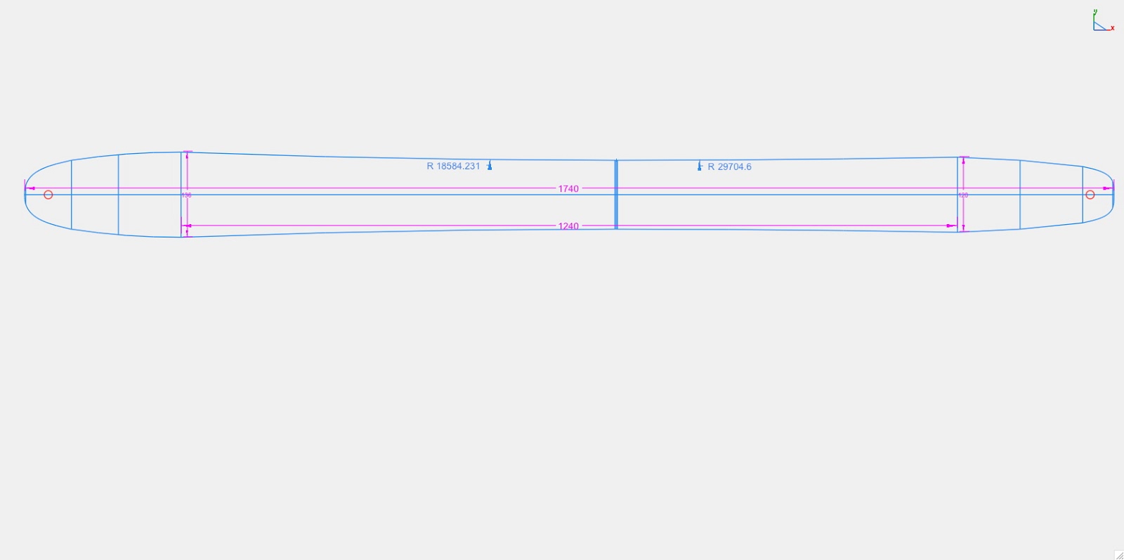
This is what I've come up with recently
This is basically drawn as I described in my last post.
This is basically drawn as I described in my last post.
Fighting gravity on a daily basis
www.Whiteroomcustomskis.com
www.Whiteroomcustomskis.com
I'm on the same page as arild.(Using DraftSight aswell) The spline tool can be an obsession...  and the mirror tool.
I'm using circles instead of straight lines when setting up the tip, waist and tail width. Personally I get a more accurate feeling where to put them, with circles, just for positioning. But thats just me..
I'm using circles instead of straight lines when setting up the tip, waist and tail width. Personally I get a more accurate feeling where to put them, with circles, just for positioning. But thats just me..
Forgot to mention that I do use the circle tool when setting up my widths (trim the line inside the circle, delete circle..OAC wrote:I'm on the same page as arild.(Using DraftSight aswell) The spline tool can be an obsession...
I'm using circles instead of straight lines when setting up the tip, waist and tail width. Personally I get a more accurate feeling where to put them, with circles, just for positioning. But thats just me..
Some progress on drawing skis and creating offsets for tip and tail spacers as well as base outline vs. completed ski dimension.
After I got my shape dialed in if offset the outline 2.2mm inward to create my base/template drawing (yellow lines). I also created an offset in the tip and tail for a pattern to make tip and tail spacers (white lines).
I also figured out how to smooth out any blocky looks in the arcs. This dealt with at what resolution the arc is drawn and at what angle the line segments are joined, or something like that.
Snocad is great but a real cad program can do a lot more. I does take some practice, trial and error as some foul language but I think I have it nailed down now.
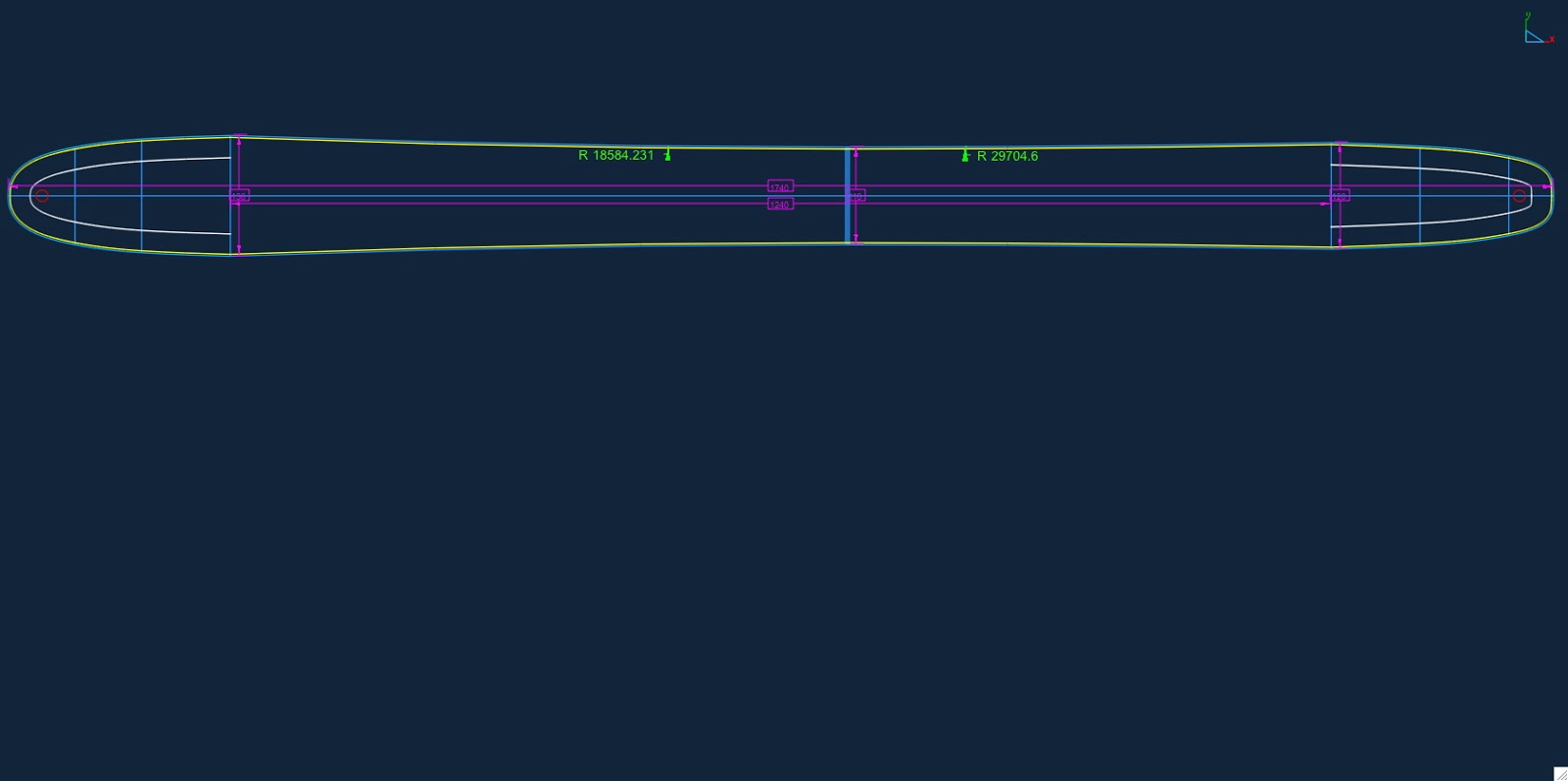
Fighting gravity on a daily basis
www.Whiteroomcustomskis.com
www.Whiteroomcustomskis.com
Hi
I know my way around cad but for some reason i cant make the dimensions work.
Mainly the tip and tail widths and lengths.
Im drawing a twin tip board thats is 1620mm in length.
260mm wide waist
and 300mm wide tip and tail.
My problem is that when i do this, i can seem to get a perfect curve for the ends....
If i use the 3 arc tool then where the effective edge ends and the tip starts, it look asthough the 'curve' is too wide at that point.
So i tried drawing a circle......if i do thsi then the tip and tail length is not the length i wanted anymore....
Can anyone offer some help? Is it best just to use either the tip length OR width and let the rest work itself out...?
I Hope this has made some sense.......
Thanks all
L
I use the spline tool. I usually use 4 or 5 points to get a smooth curve at the tip. These are usually the fat point of the tip a point somewhere near the mip point of the tip, a point 2-4mm from the end the the ski and at the very end of the tip on the center line. Connect the dots with a spline tool and smooth your curve.
Fighting gravity on a daily basis
www.Whiteroomcustomskis.com
www.Whiteroomcustomskis.com
-
mikemigs10
- Posts: 21
- Joined: Mon Jul 26, 2010 9:20 am
I am so happy I found this thread. I just down loaded a cad program because board crafter was not working for me since my pc died on me and now I am only mac. I tried using parallels to use board crafter but all my designs for some reason don't transfer. I can open the file but the board looks like i have just started.
Anyway i am a noob at cad but from the looks of the thread i should be able to get some good info to start my self off.
Anyway i am a noob at cad but from the looks of the thread i should be able to get some good info to start my self off.